3D print a QR code for this site for ACS Spring 2024
- Prepare the code
- Convert the code to 3D models with Blender
- Slice and print
- A problem due to the design
- Coated print
Another year, another ACS Spring meeting. I will be in New Orleans next week to attend this year’s Spring meeting. Since this site is already up and running, it could be useful resources when I social network during the meeting. Bringing a QR code with me came to my mind. I could easily print the code with a printer, but I felt it would be too boring. As a result, I decided to make it 3D. To do this type of 3D printing, changing the filament during printing way is almost mandatory, unless you want to paint the code yourself to distinguish it from the base.
Prepare the code
There are a number of websites that can generate QR codes. This time I used the site called QR Code Monkey. It allows you to customize almost everything of the code for free. Normally, I will change all possible elements (logo, body shape, eye ball shape, eye frame shape, and colors) to make the code as personalized as possible. However, this time, the colors completely depends on the filaments I use, so there is no need to customize the colors.
As for the logo, I do not have a good logo for my website at this moment, so I decided to make a simple text logo of “SCAN ME”. Graphical design is not at all my expertise, so I use logo.com to design a simple logo for free.
Here is the designed logo.
![]()
Here is the resulting QR code.

Unfortunately, the design of the body shape turned out to be a huge problem later.
Convert the code to 3D models with Blender
It is very convenient to import svg images into Blender. However, for this code, the logo and its frame are always separated from the code in the imported curves.
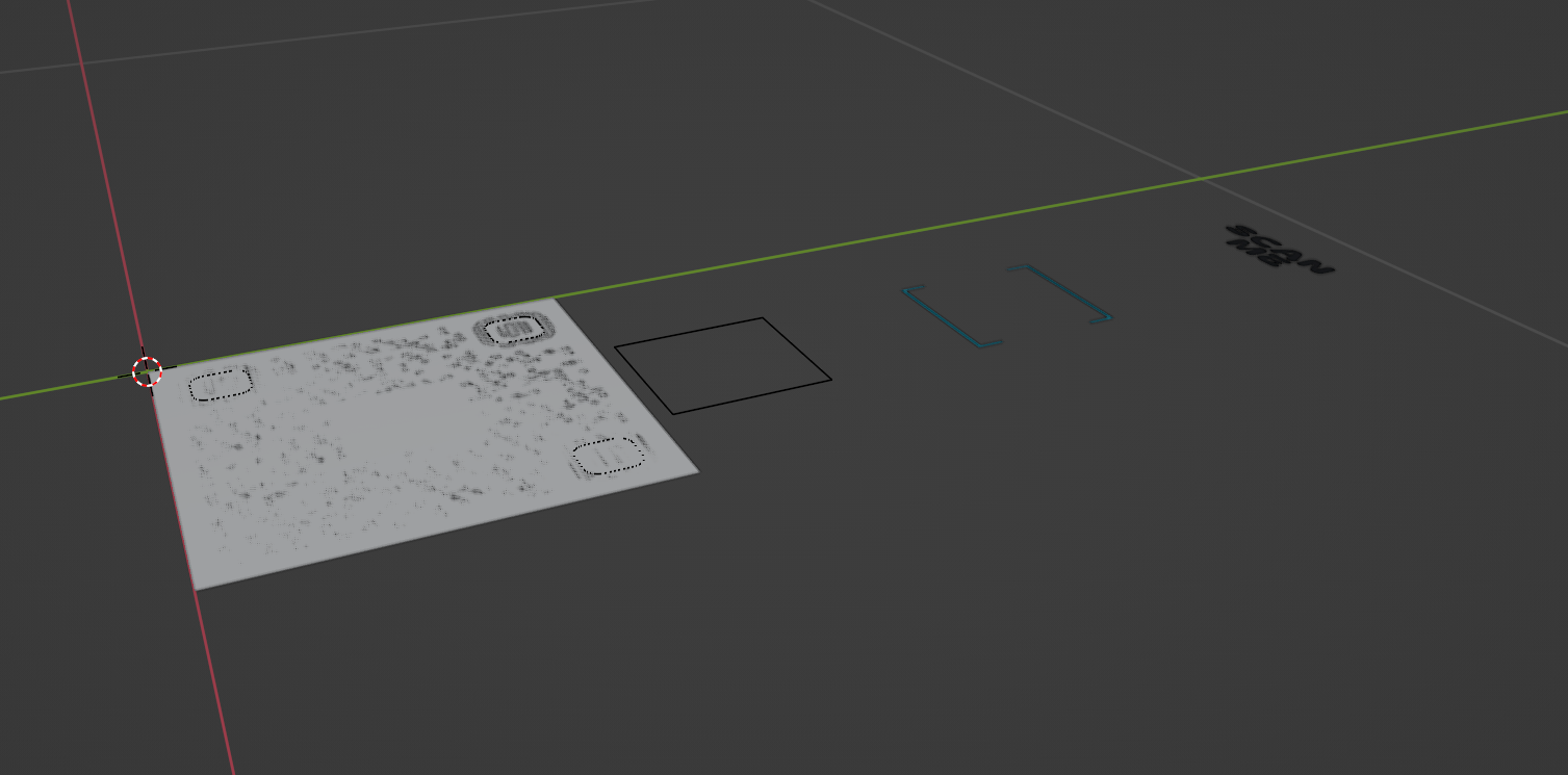
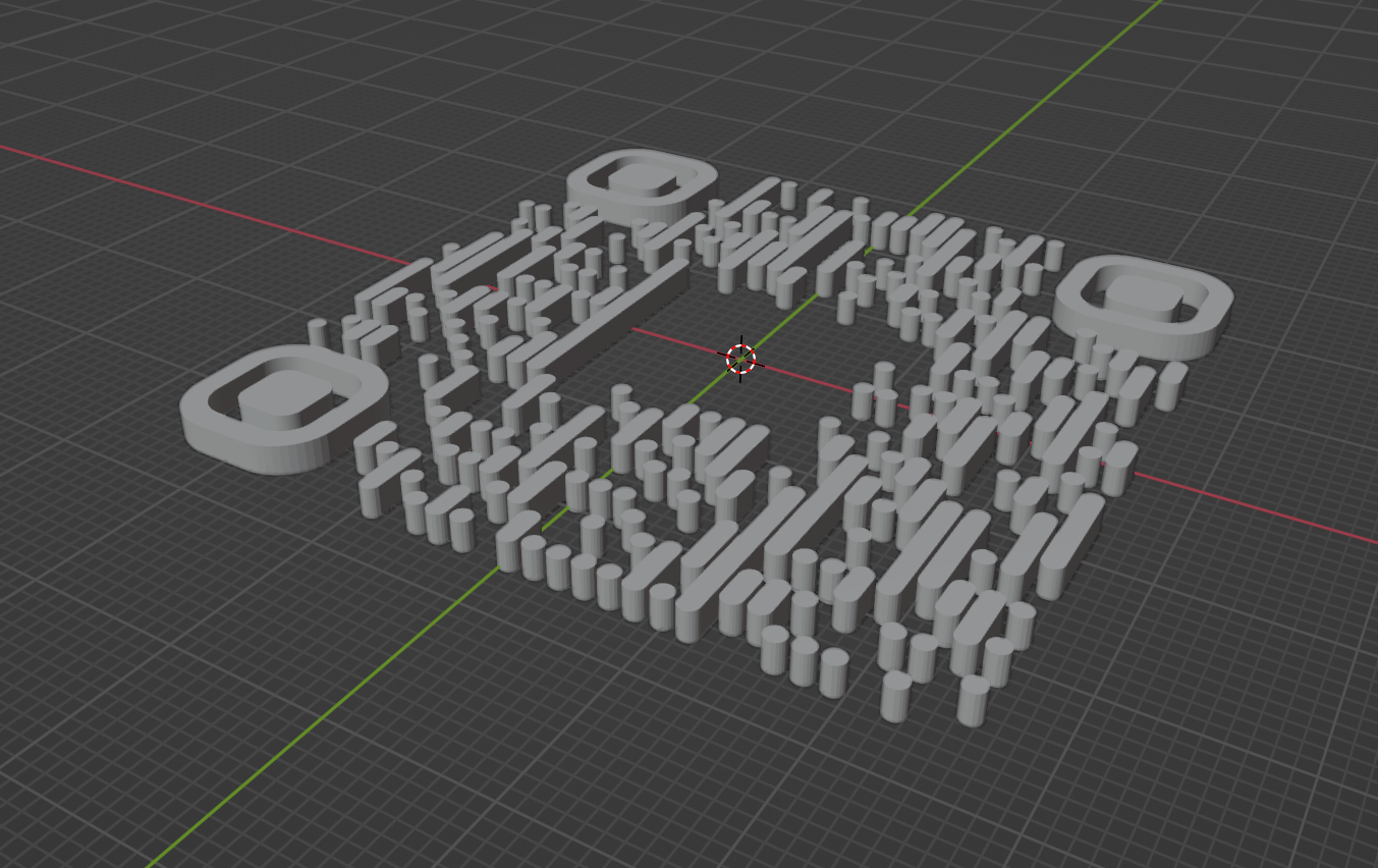
This is a small issue; I just need to reset the origin of all curve to its geometrical center and recenter everything to 0. As all dots and bars in the QR code were imported as individual curves, I also joined all the bars and dots before moving.
Now we can convert all parts to 2D meshes. Before solidifying/extruding them directly, we should simplify and fix the meshes first. Directly using meshes converted from curves can cause many problems later.
Here are the things I did.
-
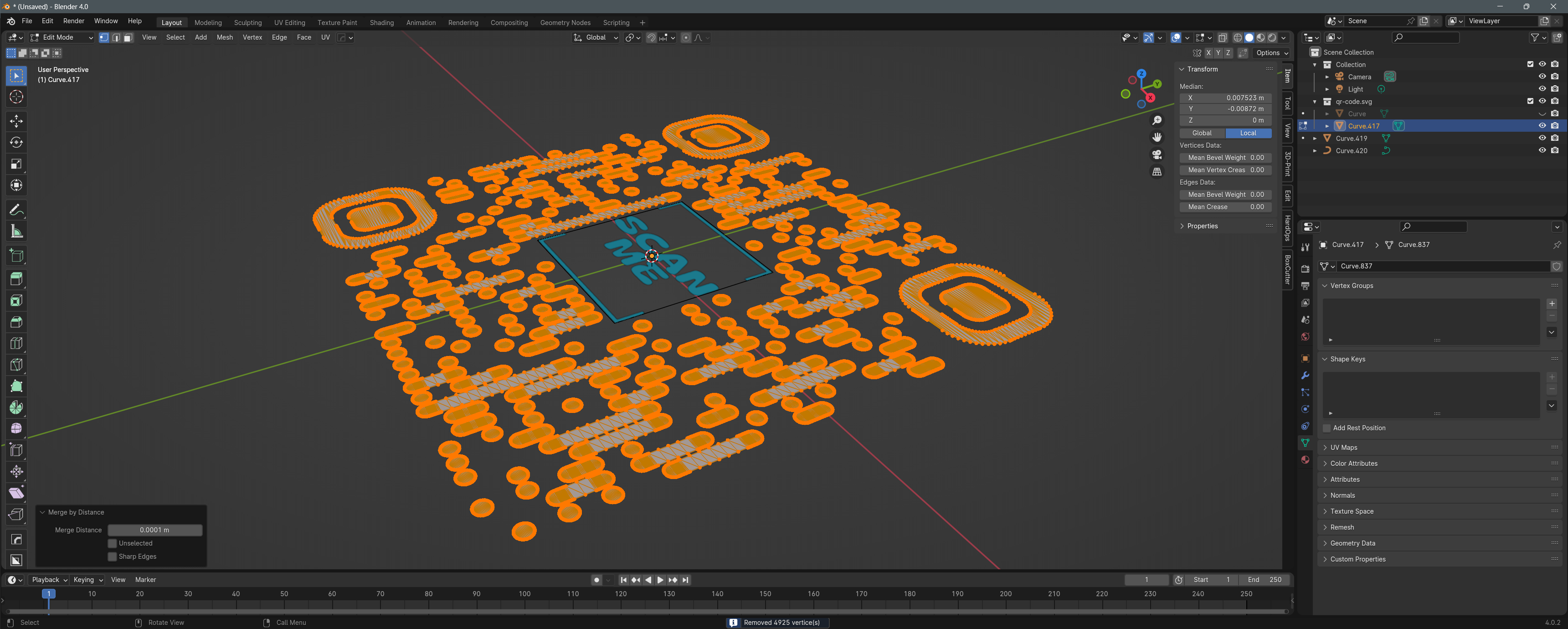
Select all vertices and merge overlapping ones. As the original svg has paths with overlaid start and end points, joining the curves and converting the curve to mesh will result in vertices with exactly the same coordinates. Merging by distance will help us a lot.
-
Remove unnecessary colinear vertices with limited dissolve. Many vertices are completely colinear, but they might be associated with some weird edges/faces which will cause problems later. As they are completely colinear, we can use the “limited dissolve” method and limit the angle to a very small number (say 1°) to safely and completely remove all of them.
To do this, select all vertices, press
Xfor the delete menu, selectlimited dissolve, and set angle 1.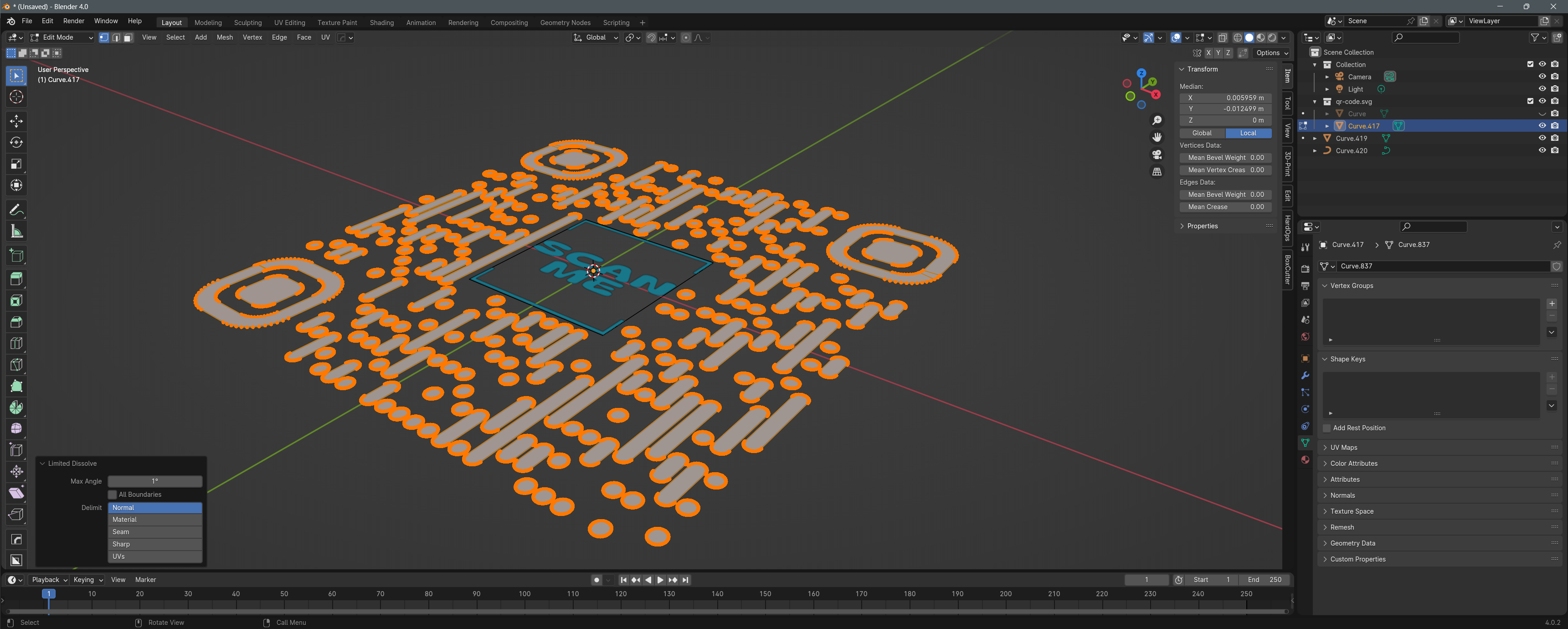
Without doing this, the weird edges from excess vertices converted from curves will cause problems to the solidify modifier.
-
Optionally, you can further reduce the number of vertices. The overall size of the printed code will only be a few centimeters anyway, the mesh does not have to be of extremely high quality.
Then you can use the solidify modifier or directly extrude in the z axis to make the mesh 3D. You should not see any erroneous faces in this step.
In fact, we can already slice the model in the current shape and send it to the printer, but I decided to add some niche changes.
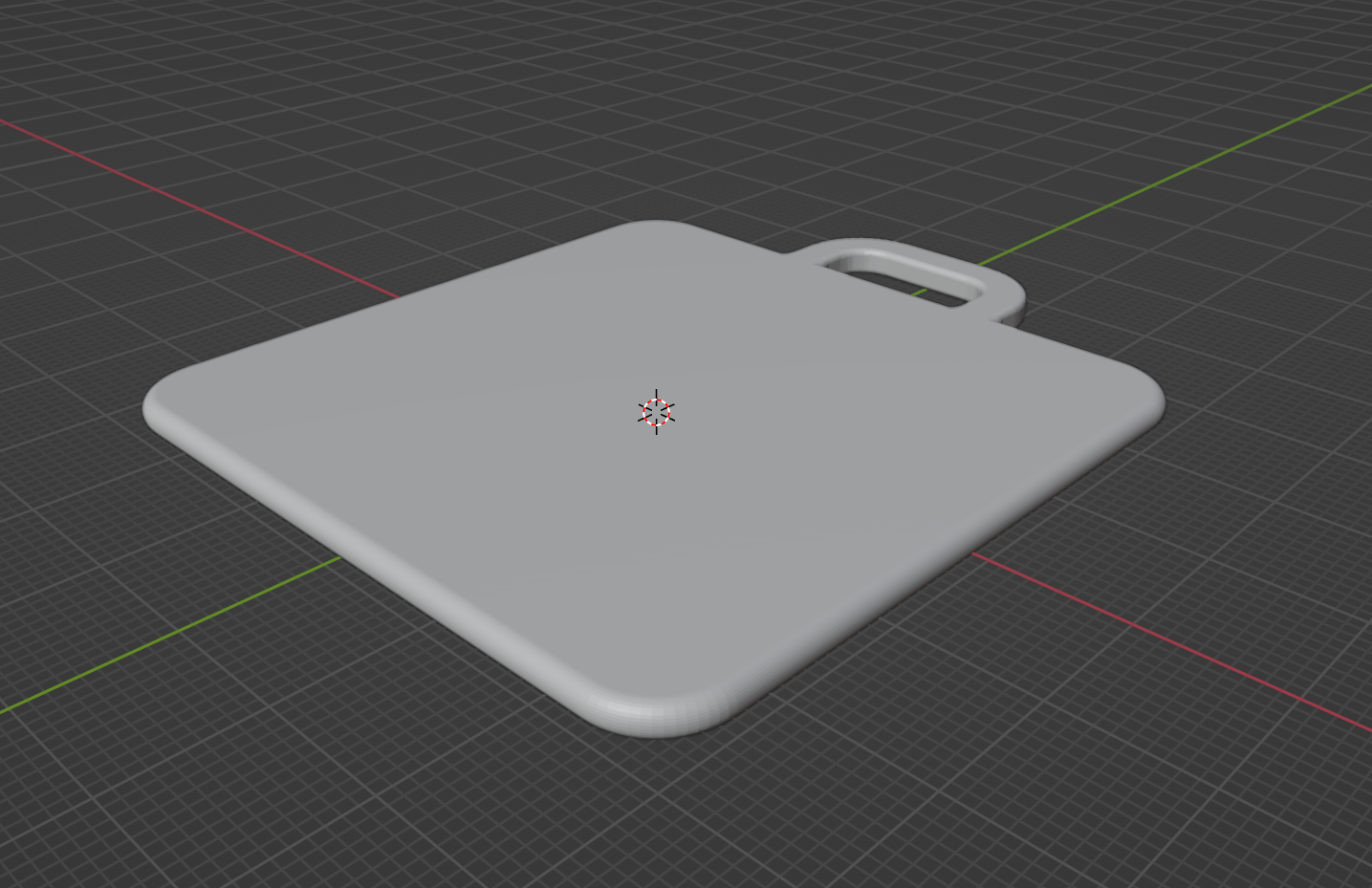
Add a slot for clips
It will be convenient if I can attach the printed code to something like a lobster claw clasp, so it can stay together with the badge assigned by ACS. If you want to know how to “extrude” a curve following the shape of another curve, here is an excellent tutorial.
You can simply add a U-shaped object and then unify it with the base through a Boolean operation.
Bevel the edges
The base will look a lot better with beveled edges. I used a mixture of directly beveling in the mesh and the bevel modifier (with different weights assignment) to achieve this. Using different weights on some edges (or even 0 weight) can solve some erroneous faces from the bevel modifier.
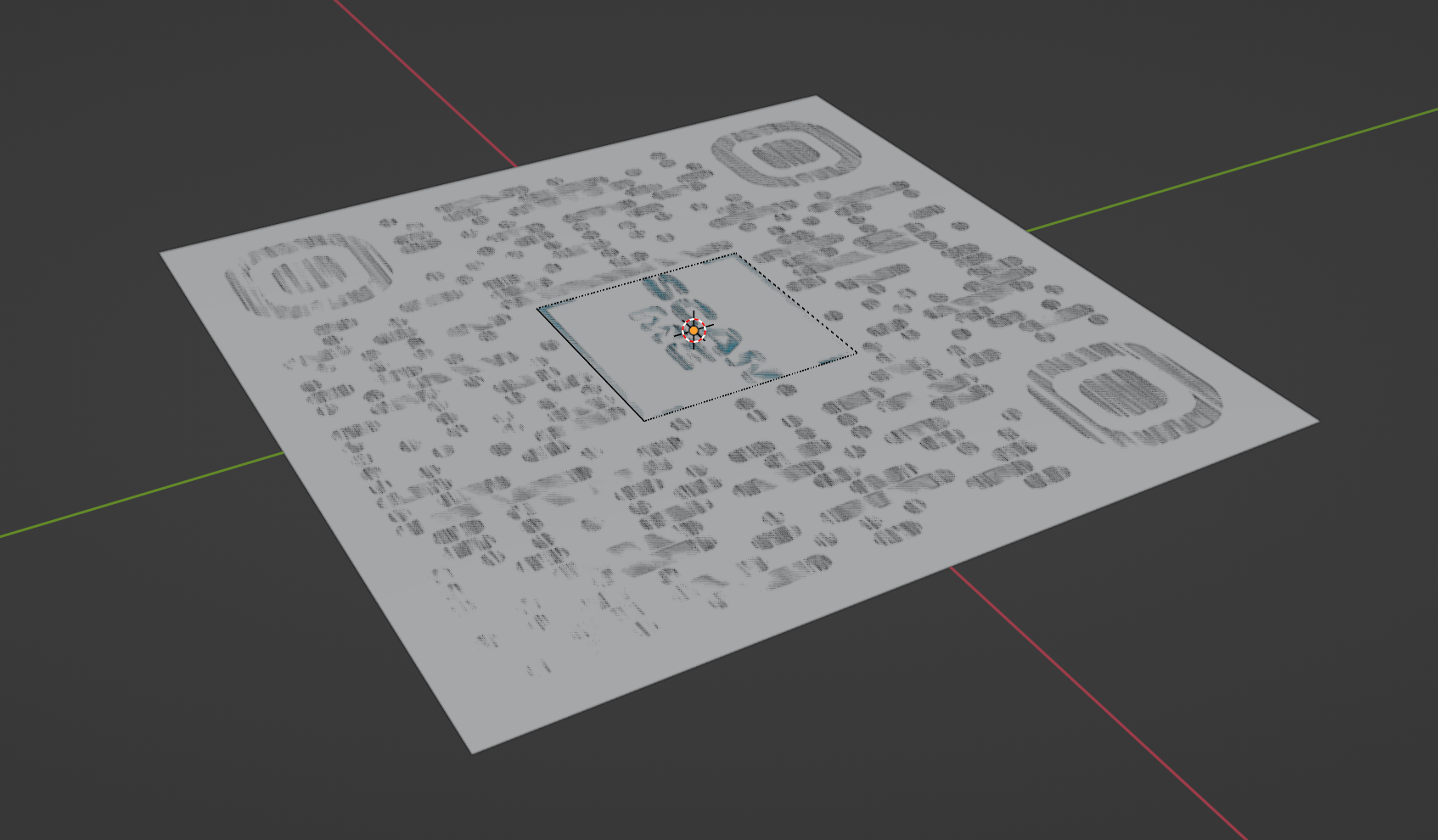
Make the logo a separate part
With this step, I can easily swap the logo later if necessary. The only object needs to be printed will be the new logo. This step is rather simple, you just have to create a separate base for the logo and do a Boolean to subtract this base to the base of the whole code. Just remember to add some tolerance on the female side. For my case, I have to give a 0.5 mm spacing on each side.
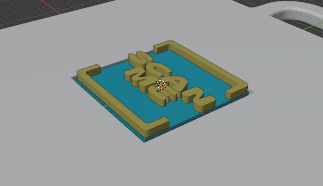
Notice the gap between the base of the logo and hole in the base.
Make sure the printed model can be scanned
This step is more like a quick way to know how likely the printed version can be scanned. If the one showing in Blender can be scanned, the printed one should likely be ok.
In the top view (z up), I zoom out the view and used a caliper to measure its size, until the size on the screen matches its physical size.
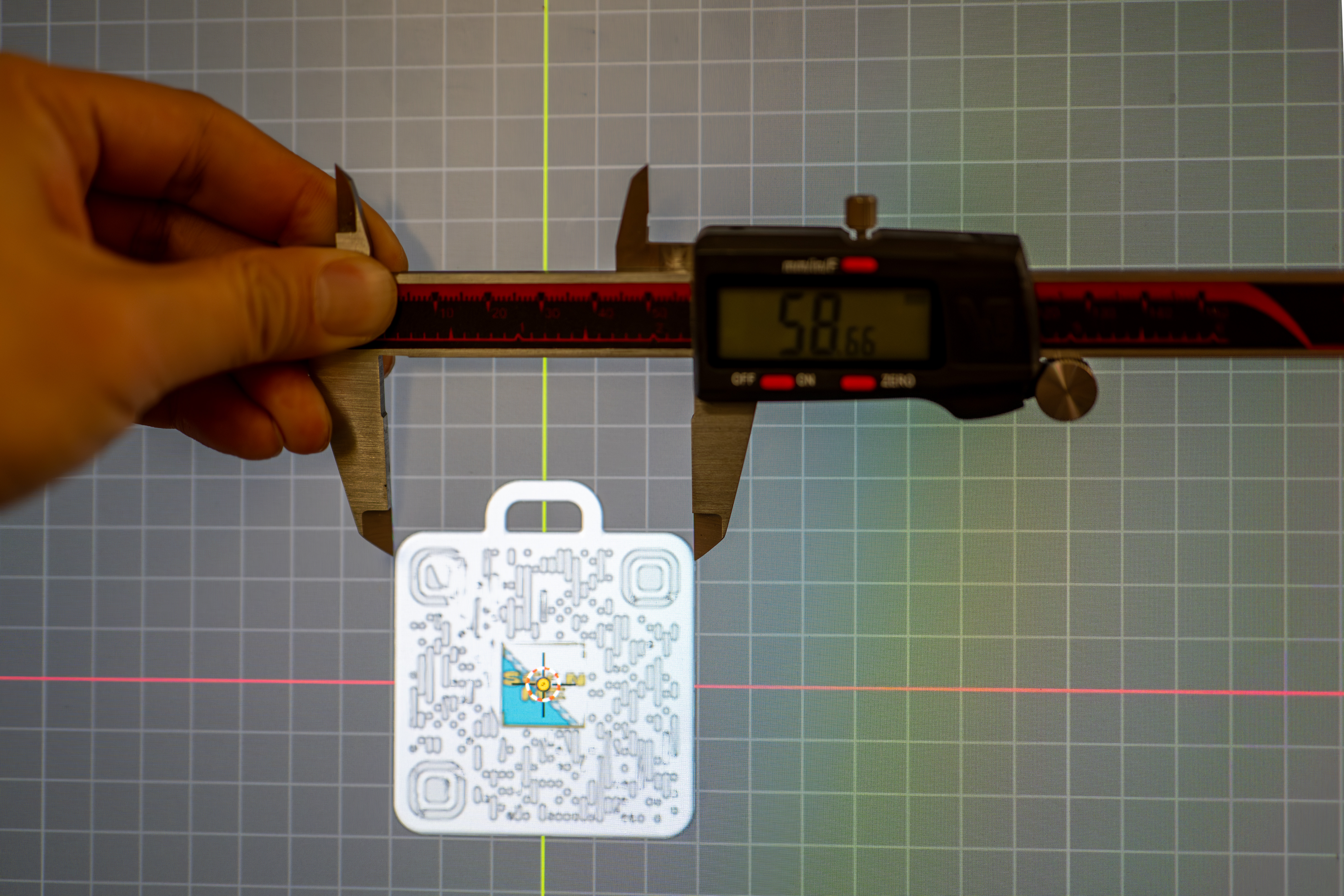
Then I used my phone to test if the model can be scanned. This image also shows the infamous PWM problem of OLED at low brightness.

Slice and print
Next, I will export the models as stl and slice them with Cura. As this part requires almost no strength, I can use some low infill rate like 15%. It is necessary to change the filament and you can easily achieve this using the “post-process” menu to add a command to pause the print at a certain layer. You need to know the layer number, so you can slice the model first, determine the layer number in the preview mode, type the number in the post-process script dialog, and re-slice the model for the final G-code.
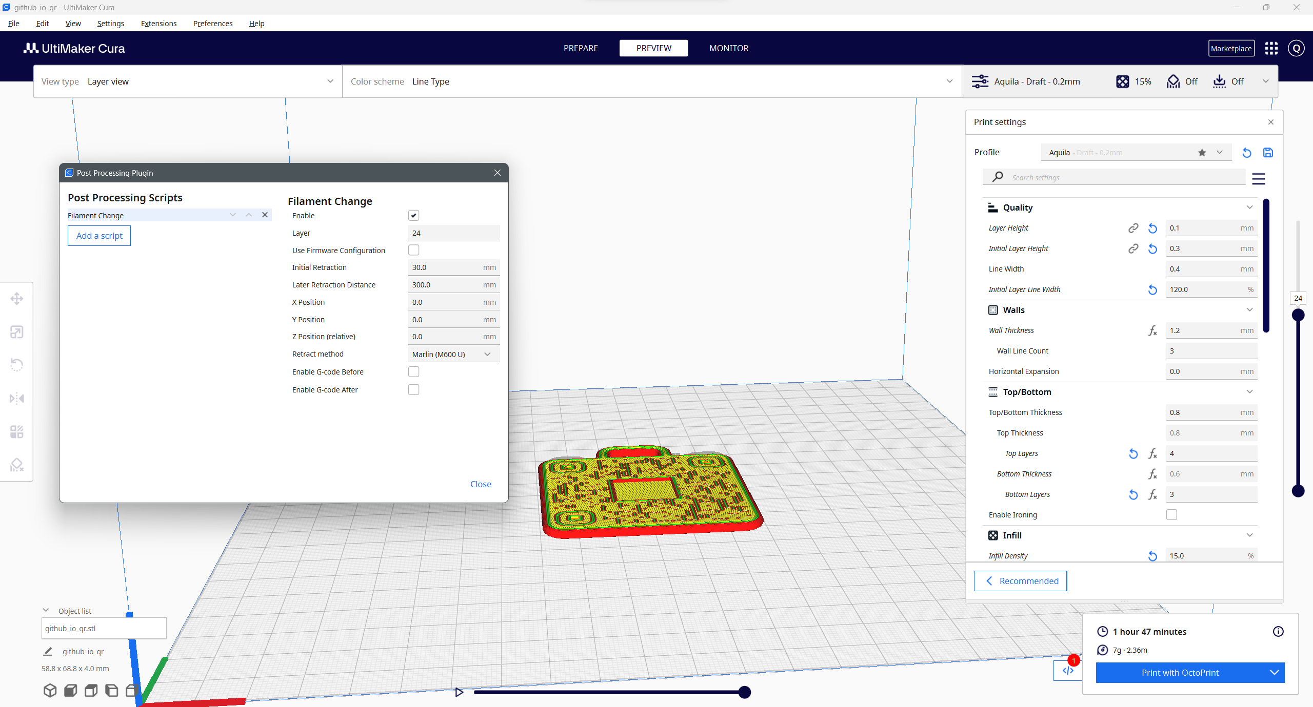
With this setting, the printer will pause at layer 24, retract the filament, and reload the new one.
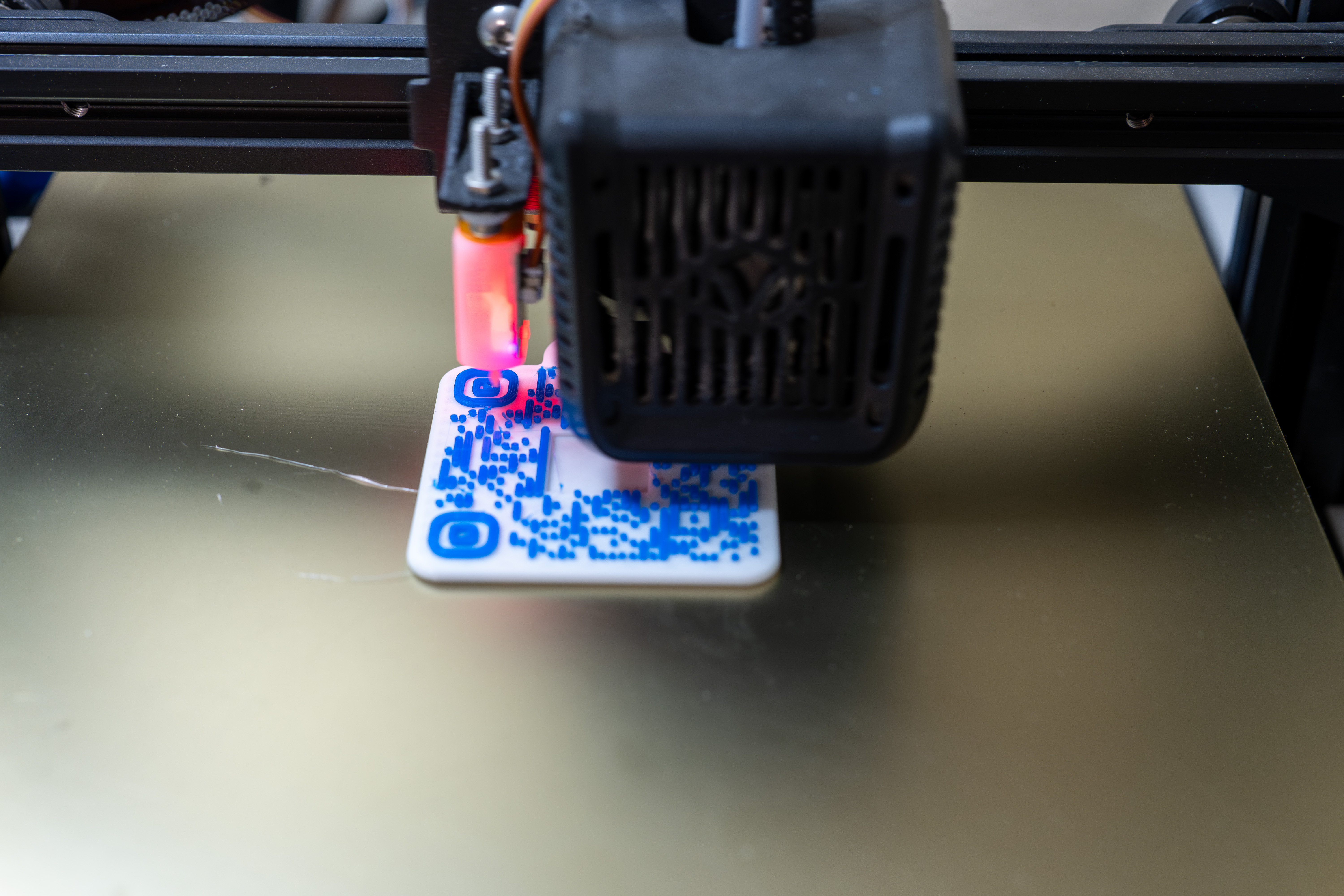
Next, I will send the G-code to the printer through Cura’s OctoPrint plugin. Then I just have to wait until the layer where the filament needs to be changes, go to the printer to swap the filament.
The first attempt of the logo print was failed. Green filament did not result in enough contrast against the white base and it is a little larger to fit in the slot on the code, so I had to reduce its size by 0.5 mm on both x and y (now the spacing is what I said in the previous section).
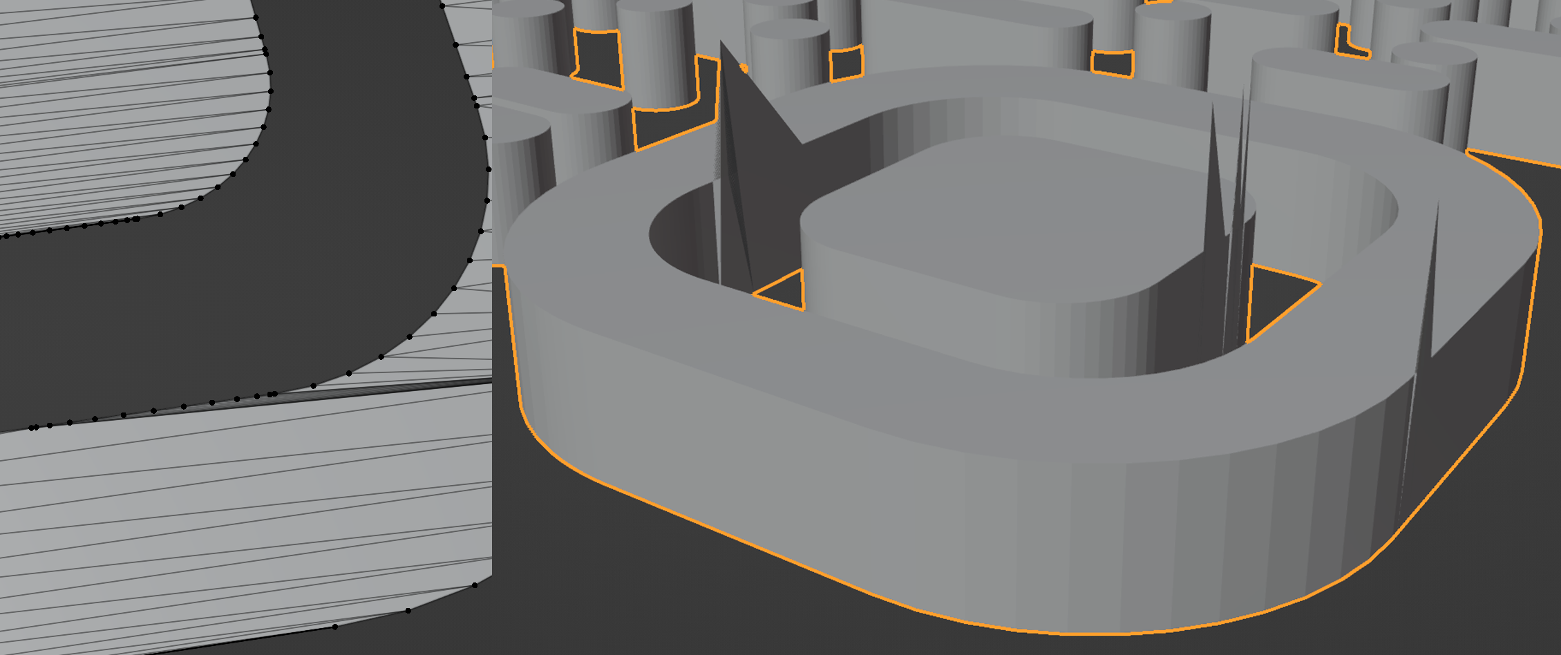
A problem due to the design
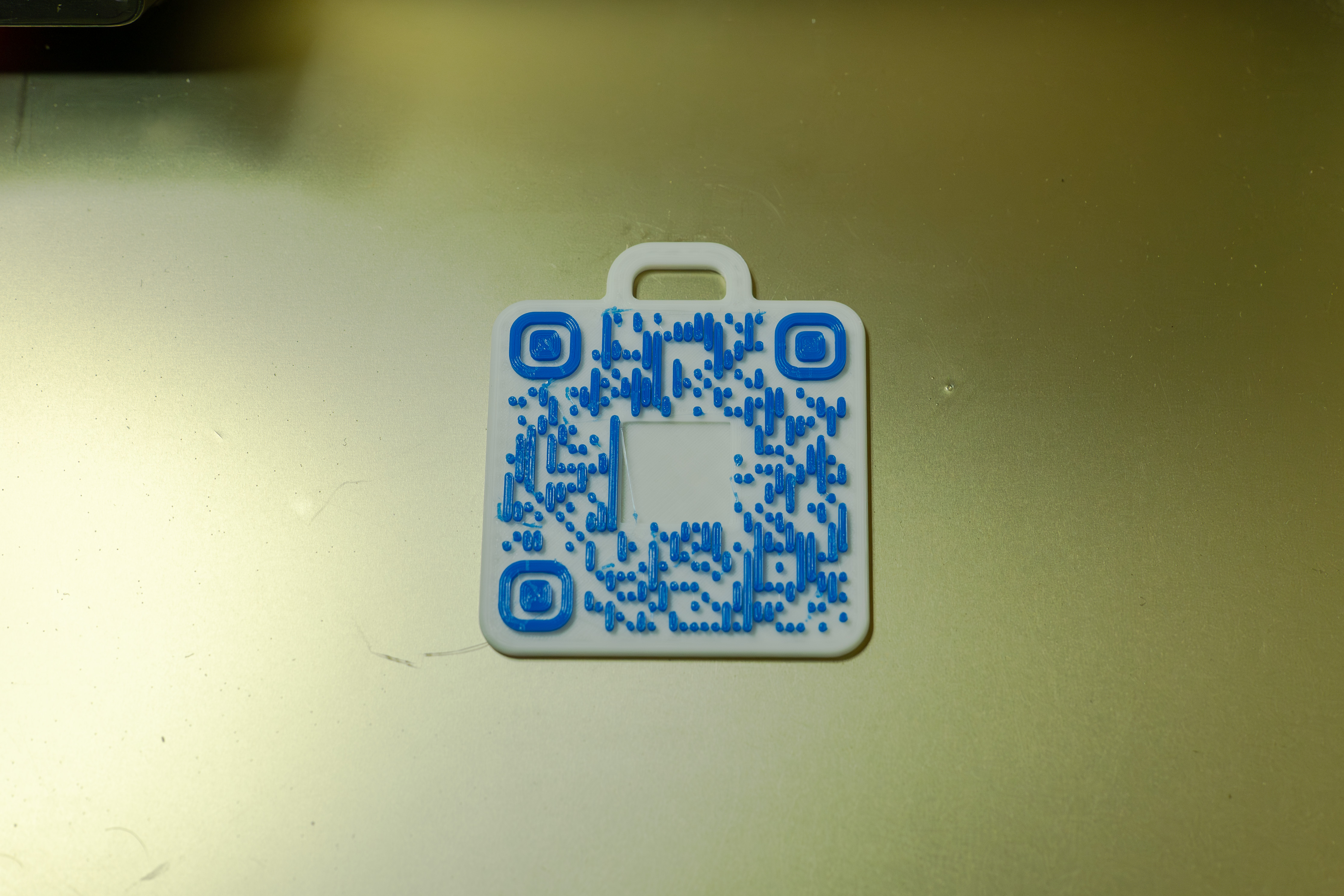
All bars and dots are separated from each other in the code. Because of this, the bond between these tiny dots and the base is rather weak. Even worse, swapping the filament made the adhesion even weaker. The dots easily break off from the base upon touches. I decided to apply a thick layer of epoxy to wrap the whole code.
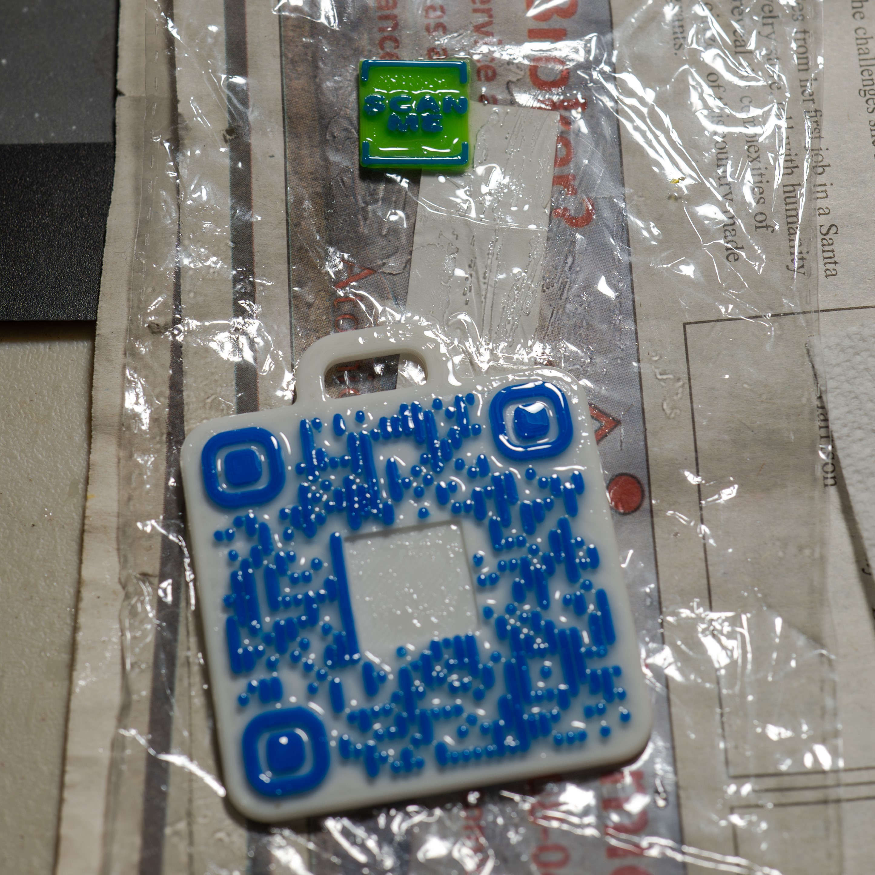
From here you can see these inclined dots. They were broken and then glued back with epoxy. They were so tiny that a precise placement was not possible, especially when they were floating in the liquid of epoxy. Did you spot the broken dots?
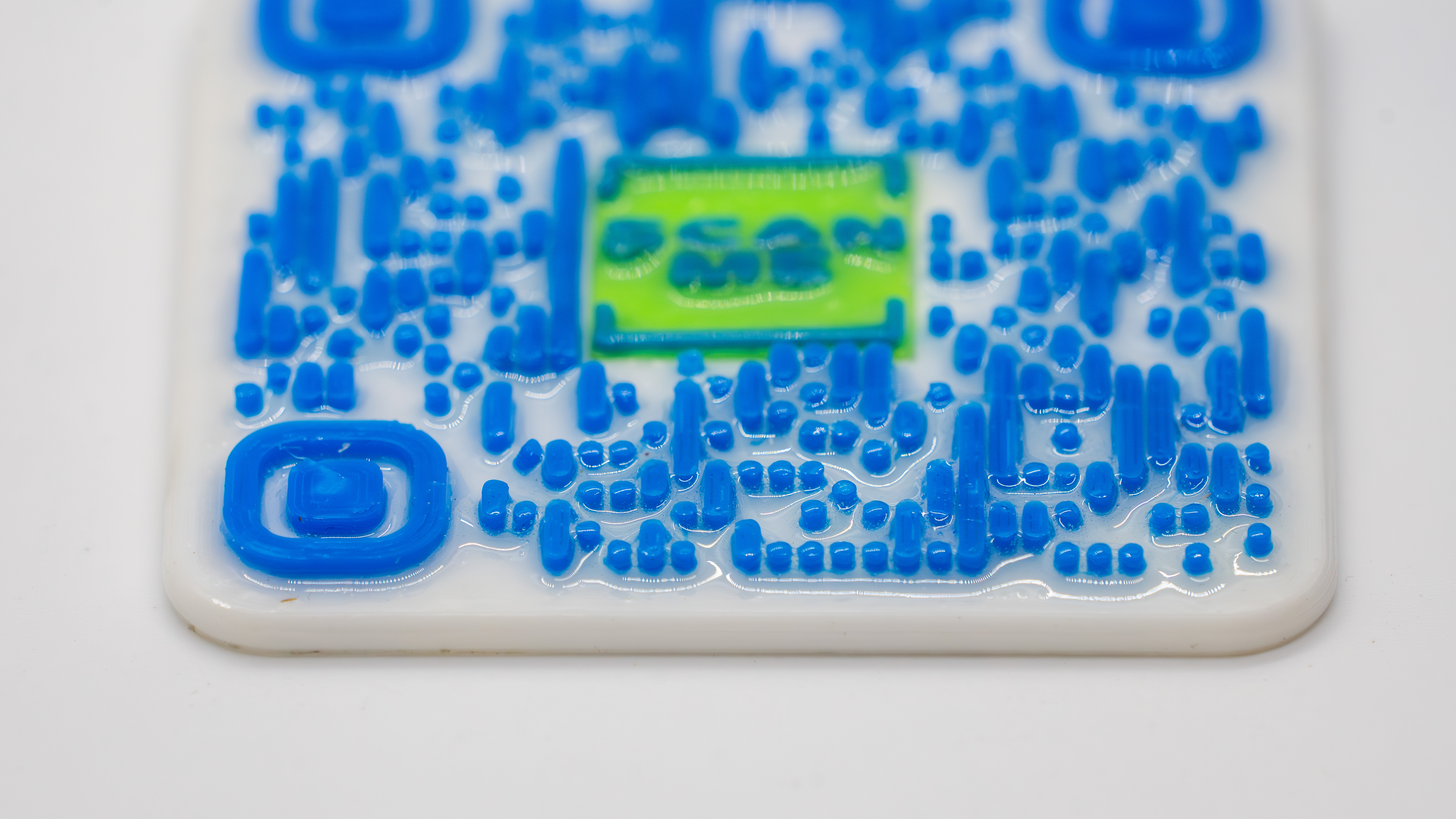
What surprised me was the redundancy in the code. There were 3 broken dots, but the code could still be scanned correctly. However, I still decided to coat the code and glue the broken ones back, just to make sure the code can be as intact as possible. After all I cannot print a new one during the ACS meeting.
However, if I print a QR code again in the future, I will definitely choose a design that the pattern is as continuous as possible to minimize issues like this. Still, these lone dots will likely exist in any design pattern. Now, I have question. As we all know some of these dots and bars are alone for redundancy, it is possible to generate a code that does not have these lone dots? For example, just two adjacent dots forming a bar will make the 3D print much stronger. If you happen to know the answer, could you post it in the comment section below?
Coated print
Now, the epoxy is fully cured. Here is how it looks like with my LANL lanyard.
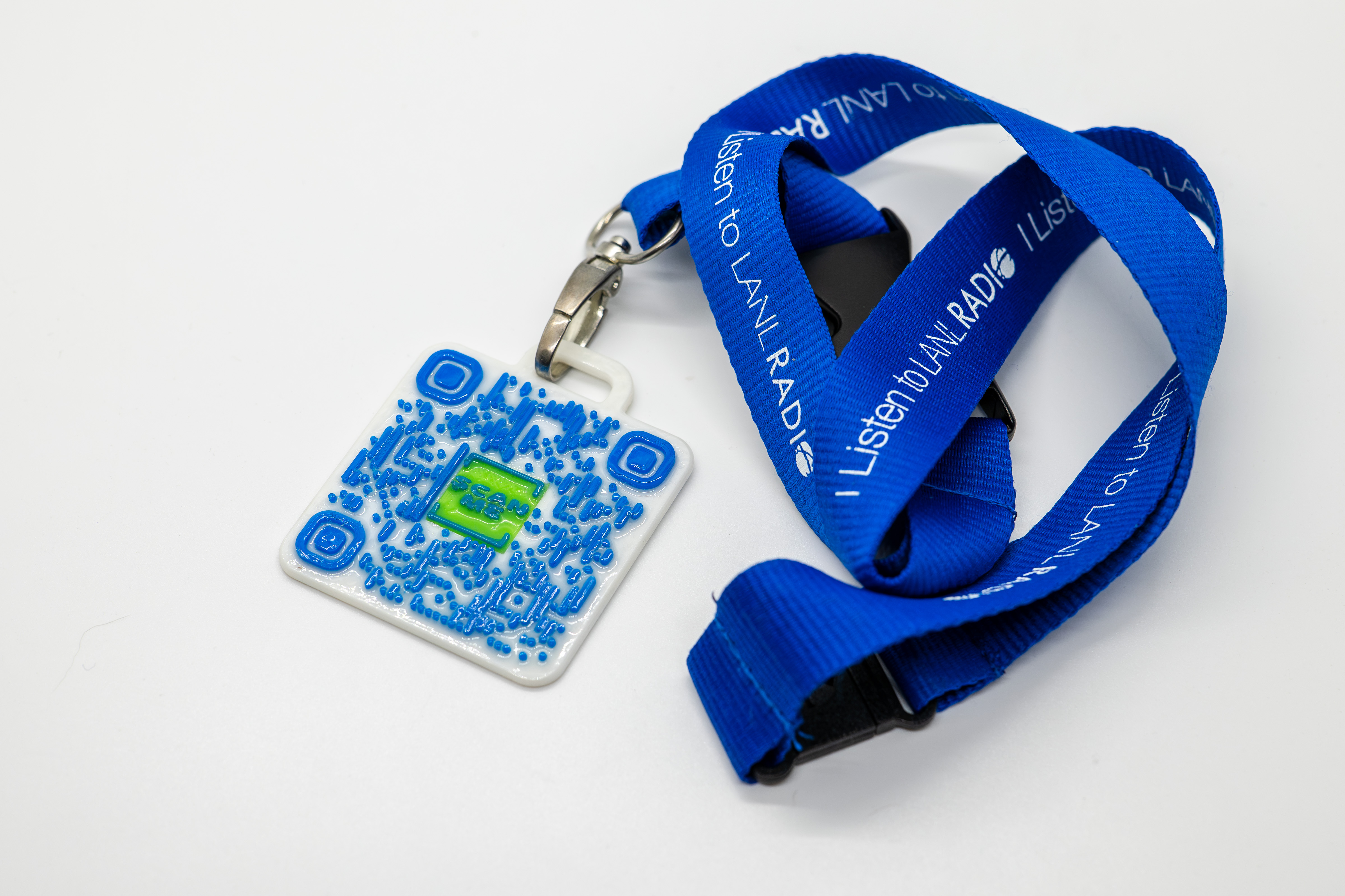
See if anyone will scan the code and find this post at ACS!
Originally published on March 13, 2024.Home Lab 3D Printing DIY